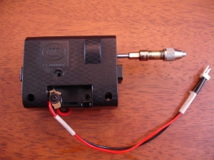
After many broken drill bits and a sore index finger, for the past few days I was planning to build myself a PCB Drill. I do a few PCBs every month at home and the hardest and messiest part is drilling the holes manually. I have an old PCB hand drill which I had bought a few years back, but since I do only a couple of PCBs once in a while, I do not want to invest in a commercial PCB drill or drill press which costs a lot of bucks. I also have a regular size electric drill and I have tried to drill PCBs which did not work out well due to its size, weight and noise. I have read on the internet how to build a rig to support a regular size electric drill for drilling PCBs, though it never appealed to me due to the size factor!
There are many disadvantages of using a manual hand drill except that it is ‘green’ to use 😉 , Though it is definitely not cheap after a couple of broken drill bits which are expensive to replace.
So I stumbled upon an idea to use a totaled RC toy car of my 4 year old to make a PCB drill. There was not much left of the car itself, the front steering mechanism and the rear drive motor & gear assembly were still intact. The build process is simple and will take couple to hours to build if you already have a spare PCB hand drill/drill chuck, a broken RC car and few other parts at hand.
So here we go, The idea is to mount the drill chuck on to the wheel shaft of the RC car and provide basic controls to start/stop the drill and change the direction of rotation. A 5V wall wart provides juice to the drill, if you want you can also use a battery pack, (4 X 1.2V) AA size rechargeable or (3 X 1.5V) regular AA alkaline.
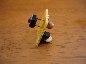
For direction control, I have used a dual pole sliding switch wired for polarity-reversal and for on/off control a switching NPN transistor activated by a tiny tact switch. The circuit uses only a few components, so I have used a small strip board to mount them and the circuit board can be squeezed inside the motor and gear housing.
I have documented the build process with photos, so follow along… Check out the video of drill in action at the bottom.
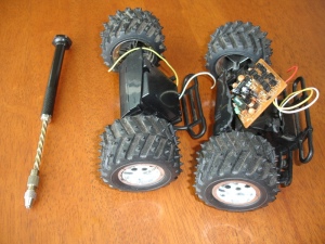
As you see, there is not much left of the car. Also, the RC circuit board contains all the components you will need to build the control for the drill (except switches). On the left is my old PCB drill.
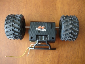
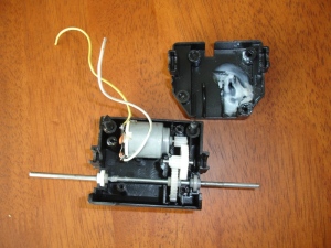
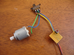
To make the drill, we will need the drive motor and gear assembly. In the above image the motor and gear assembly with power leads for the motor.
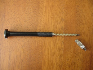
Take apart the chuck from the hand drill.
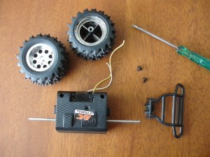
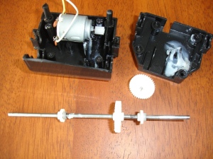
Take apart the RC car motor and the gear assembly housing. Notice the blob of unused grease inside the top housing. I saved it to re grease the gears during the final assembly.
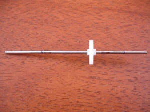
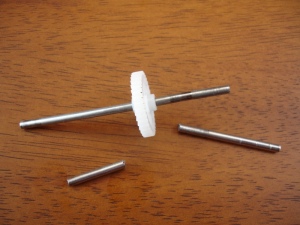
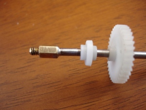
Remove the wheel shaft, wipe the grease off , mark and saw off the excess shaft from both the ends.
This was the hard part! I do not have anything to cut threads on the shaft, so after searching a while for a suitable adaptor to attach the drill chuck, I found the PC motherboard mount (the little brass thingy), It was a snug fit on the shaft and the screw end mated perfectly with the drill chuck. To make the joint stronger, I soldered the shaft and the brass mount together. Couple of things you need to take care before you solder, insert the nylon bush before the brass adaptor, and while soldering make sure you do not overheat the shaft as it may damage the nylon bush and gear. After soldering, file off the excess solder and finish using a fine grain sandpaper.
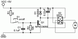 Here is the schematic for the motor control. It uses only a few components, most of which are salvaged from the RC circuit board. The transistor is a general purpose NPN, if you cannot find C8050, you may try 2N2222A or an n-channel MOSFET BF170, but make sure the transistor is rated for atleast 1A continuous current. The transistor is normally in cut-off state (non-conducting) as the base is held low by R2. When the tact switch S1 is pressed the base of the transistor is pulled high and transistor conducts supplying power to the drill motor. D1 and C2 are used to suppress the voltage spikes when the motor is turned off. Switch S2 is a dual switch and it selects the direction of rotation by reversing the polarity of power supplied to the motor.
All the components including the tact switch are mounted on a small piece of a Perf board.
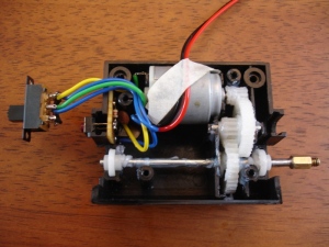
All components and wires soldered and everything back in the box!
The dual switch for direction control and the red push button switch for on/off.
And here is the video of drill in action:
Till next time, Happy Hacking! and please leave your comments what you think about this hack.
Bye for now!
